Application
:Introduction to Terminology
What is an FPC board?A printed circuit board with a copper circuit formed on a thin, soft insulating film.It is also called "flexible printed circuit board," "flexible substrate," or "flex board."
Unlike typical rigid circuit boards, FPC circuit boards have the significant characteristic of being bendable. They are used when wiring is needed in narrow spaces, when wiring needs to be bent to match the shape of equipment, or when wiring is needed in moving parts.
However, FPC boards are not just "flexible boards."
The choice of materials, type of copper foil, bending location, method of reinforcement, and the presence or absence of component mounting all affect usability and durability.
What is an FPC board? It's easy to understand if you first think of it as a "bendable board for wiring."
FPC substrates areA circuit board used to connect components within electronic devicesIt not only serves as a rigid substrate for mounting components but also plays a role in routing wiring like a cable.
For example, in a smartphone, many components such as cameras, displays, batteries, and sensors are housed in a limited space.
In such a location, if you try to wire using only rigid printed circuit boards, you may run out of space or reduce the freedom of component placement.
Using FPC (Flexible Printed Circuit) boards allows for the placement of thin film-like substrates while bending them.
This makes it easier to create three-dimensional or folded wiring, leading to smaller and thinner devices.
In other words, FPC boards are not just "flexible boards," but also wiring components that make effective use of limited space inside a product.
What's the difference between FPC, flexible circuit board, and flex board?
These are,Words that are often used with almost the same meaning
- FPC: Abbreviation for Flexible Printed Circuits
- Flexible circuit board: A general term referring to a board that can be bent.
- Flexible circuit board: Commonly used abbreviation in the field and in conversation
- Flexible Printed Circuit Board: More Formal Expression
Strictly speaking, "flexible printed circuit board" is used in formal documents, but in searches and practical applications, "FPC board," "flexible board," and "flex board" are also commonly used.
Reasons why FPC boards are used
The reason FPC boards are chosen isn't just their flexibility.
Thinness, lightness, wiring flexibility, and reduction in the number of partsThere are multiple benefits, such as:
What's particularly important is that it's easy to accommodate the "tightness" inside the product. Electronic devices are becoming smaller and thinner, and the usable space inside is limited. FPC boards are thin and can be folded and arranged, making them suitable for wiring that would be difficult with rigid boards or cables alone.
- Can be wired in narrow gaps
- Can be placed in a bent state
- Connect parts three-dimensionally
- When possible, reduce cables and connectors.
- Helps to make products smaller and lighter
- It can sometimes be used for wiring in moving parts.
On the other hand, FPC substrates cannot be bent freely and repeatedly.
Depending on the bending position, bending radius, number of bends, and circuit shape, there are risks of disconnection or degradation.
Therefore, when using FPC boards, it's necessary to consider not only "whether it can be bent" but also "how it can be bent."
Difference between FPC substrate and rigid substrate
To understand FPC boards, knowing the difference between them and rigid boards is a shortcut. Rigid boards are the common, hard printed circuit boards.
Rigid substrates are used as a base for mounting components and creating circuits.
Because they are solid boards, components can be mounted stably, but they cannot fundamentally be bent for use.
FPC boards not only hold components but also serve as wiring materials.
Because it is thin and soft, it can be passed through narrow spaces, bent, or used to connect parts three-dimensionally.
| Comparison items |
FPC board |
Rigid substrate |
| Shape |
Thin and soft |
Hard, flat board |
| Flexibility |
Can be bent and placed |
Basically unbendable |
| Primary role |
Wiring, connections, and component mounting |
Component mounting, circuit formation |
| Suitable uses |
Space-saving wiring, moving parts, three-dimensional wiring |
Fixed electronic circuit, control board |
| Points to note |
The bend areas and mounting areas require careful design. |
Not suitable for bending applications or wiring in narrow gaps. |
Rather than one being superior, their roles are different.
Rigid boards are used for parts that need to be implemented stably, while FPC boards are used for parts that need to be bent or routed, allowing for differentiated use.
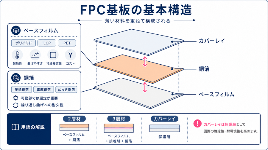
Basic structure of FPC board
FPC substrates are made by layering thin materials.
Basically,Base film, conductive copper foil, and coverlay to protect the circuit.and so on.
Knowing this structure will make it easier to understand the terminology related to FPC substrates.
Terms like "2-layer material," "3-layer material," "rolled copper foil," "electrodeposited copper foil," and "coverlay" are used to explain the materials and layer differences of FPC substrates.
Base film
The base film isThin insulating film that forms the base of an FPC substrateIt is an electrical insulator and serves to support copper circuits.
Commonly used materials include polyimide, liquid crystal polymer, and PET.
The choice of material affects heat resistance, flexibility, dimensional stability, and cost.
Copper foil is,The part that becomes an electrical circuitFPC boards use thin and soft copper foil.
Copper foil includes rolled copper foil, electrolytic copper foil, and plated copper foil.
For applications where it will be bent, the type and thickness of the copper foil affect its durability.
Especially for FPC boards used in movable parts, the selection of copper foil is important because the circuit is repeatedly bent. It is not enough for electricity to simply flow; the structure needs to be designed to prevent cracks and disconnections when bent.
Learn more about copper foils used in FPCs
coverlay
A coverlay is,Films and inks for protecting FPC substrate circuitsIt maintains insulation by covering the circuit and protects the circuit from damage and dirt.
On rigid PCBs, solder resist is often used for surface protection. In contrast, for FPC boards, a coverlay that is more adaptable to bending may be used.
The solder mask is not just about covering the circuit.
Parts where components are mounted and terminals that connect to connectors must have copper exposed.
Therefore, the design of where to protect and where to open is important.
About Coverlay
Key Differences Between 2-Layer and 3-Layer FPCs
FPC substrates are sometimes referred to as "2-layer materials" or "3-layer materials" depending on the composition of the base film and copper foil.
FPC 3-layer material is made by bonding a base film and copper foil with an adhesive.
On the other hand,A 2-layer FPC is what integrates the base film and copper foil without using adhesive.
Generally, two-layer materials without an adhesive layer can be made thinner and may have advantages in flexibility and dimensional stability.
However, the appropriate material varies depending on the application and cost.
For example, a 3-layer material may be chosen for general FPCs.
On the other hand, a 2-layer material may be considered when fine wiring or strict dimensional accuracy is required.
Learn more about the differences
between 2-layer and 3-layer FPCs
Types of FPC boards
FPC boards come in several types depending on the number of circuit layers and their application.
Do you want to bend it thinly? Do you want to increase the wiring? Do you want to place components?The suitable type will vary depending on that.
Single-Sided FPC
Single-sided FPC isFPC board with circuitry on only one sideThis is the type that has a simple structure and makes good use of the thinness and flexibility characteristic of FPCs.
For parts that are bent or in movable sections, single-sided FPCs may be chosen. However, if the circuit becomes complex, it may not be possible to route all the connections on a single side.
Double-sided FPC
Double-sided FPCs are,FPC board with circuits on both sidesCompared to single-sided FPCs, it is easier to increase wiring density, which increases the degree of freedom in circuit design.
However, the structure tends to become thick, and its flexibility may be reduced compared to a single-sided FPC.
When used in moving parts, design that considers the bending position and number of times is necessary.
Multilayer flexible printed circuit
Multilayer flexible PCBs areFPC substrate with multiple circuit layers stackedWhen dense wiring is required or complex circuits need to be accommodated in a limited space, this is used.
They are suitable for high-performance products, but the more layers there are, the more complex the structure becomes.
Since costs and manufacturing difficulty tend to increase, it is necessary to consider the balance between mass producibility and required performance.
Rigid-Flex PCBs
Rigid-flex PCBs areA substrate integrating rigid board sections and flexible FPC sections.
It allows for designs such as making the part-mounting area rigid and the bending/connecting area flexible. This can reduce the number of connectors and cables, contributing to miniaturization and improved assemblability.
However, because it tends to be more complex in design and manufacturing than ordinary FPC substrates, it is important to consult with the manufacturer at an early stage.
Main materials used for FPC substrates
The performance of FPC boards varies greatly depending on the materials used.
Can it be bent? Can it withstand heat? Is it dimensionally stable? Can it handle high frequencies?This relates to material selection.
Polyimide
Polyimide is,The representative materials commonly used for FPC substratesIt excels in heat resistance and electrical insulation, and is widely used as a base film for general FPCs.
In component mounting, heat is sometimes applied, such as during soldering.
Therefore, polyimide, which is heat-resistant, is an easy-to-use material for FPC substrates.
Liquid Crystal Polymer (LCP)
Liquid crystal polymers are also called LCPs.
Materials considered for applications prioritizing high-frequency characteristics
For example, in equipment that handles high-speed communication or high-frequency signals, the electrical properties of materials become important.
In such applications, liquid crystal polymers are sometimes chosen instead of general polyimides.
PET
PET is,Materials that are relatively easy to keep costs downIt can be used as.
However, its heat resistance is lower than that of polyimide, so it may not be suitable for applications that require high-temperature processes or solder mounting.
The choice of material will vary depending on whether you prioritize cost or heat resistance and durability.
Learn more about materials like polyimide and LCP used in FPCs
Flexible Printed Circuit Board Manufacturing Process
FPC boards are made by preparing materials, creating circuits on copper foil, protecting the surface, and if necessary, plating and shaping the exterior.
The manufacturing process is specialized when viewed in detail, but first"Circuit manufacturing process" and "Circuit protection process"It becomes easier to understand if you break it down into parts.
Circuit creation process
On FPC substrates, circuit patterns are created by processing copper foil. Typical methods include:Subtractive and additive methods
The subtractive method is a way to create circuits by removing unwanted copper foil, leaving only the necessary conductive pathways.
In contrast, the additive method forms circuits by adding copper to the required areas.
Which method is suitable depends on the fineness of wiring, the required precision, cost, and mass production feasibility.
Learn more about subtractive and additive methods
What Is Etching?
Etching isA method of processing into a desired shape by removing unnecessary parts using chemicals and the like.This is the process used in FPC (Flexible Printed Circuit) boards to create circuits by removing unnecessary copper foil.
If the etching precision is low, the wiring width can vary, and fine circuits may not be formed properly.
Therefore, it is a crucial process for FPC boards, which are used to create intricate circuits.
Learn more about the types and process of etching
What is plating?
Plating isMetal film coating processIt is used for FPC boards to make through-holes conductive, protect terminal parts, and apply surface treatment.
There are two plating methods: electrolytic plating, which uses electricity, and electroless plating, which uses chemical reactions. The appropriate method varies depending on the purpose and the metal used.
Learn more about plating techniques for FPCs
Overlay processing and external machining
After you create the circuit, you protect it with a coverlay or similar material.
However,Expose copper as needed on the parts where components are mounted and where connectors are attached.
After that, the FPC substrate is processed into a form that can be incorporated into the product.
Since FPC is thin and flexible, it is also important to prevent stress from concentrating on the outer edges and slit portions.
Things to be careful about in FPC board design
Flexible printed circuit boards (FPCs) are convenient boards that can be bent freely.
However, if the design is incorrect,Disconnection, cracks, component peeling, poor contactcan occur.
We should pay particular attention to the bent parts, mounting parts, and terminal parts.
These three areas are where FPC board failures are likely to occur.
Do not create sharp bends in the wiring at the curved sections.
If the wiring in the bent section has sharp corners, stress tends to concentrate there.
When force is concentrated, it can cause cracks or breaks in the copper foil.will be.
Therefore, make the pattern of the bend as smooth as possible.
Care must be taken to round corners, avoid abrupt changes in width, and avoid sharp angles at the connection to the land.
Do not place parts where they will be bent.
When the part with the component is bent, force is applied to the solder joint.
As a result,Parts can float, and cracks can form in the solder.
Place components on flat areas, avoiding bends as much as possible.
The basic principle is to consider bent sections and mounting sections separately.
Consider reinforcement plates for the mounting sections and terminal sections.
FPC boards are flexible, so it can sometimes be difficult to achieve stable component mounting and connector connections without reinforcement.
Reinforcement plates are attached to such parts.
Using a reinforcement plate can suppress warping of the mounting part and increase the strength of the terminal part that is inserted into the connector.
However, the position where the reinforcing plate is attached is also important.
If force concentrates at the edge of the reinforcing plate, it may become prone to breaking from there.
The range, thickness, and material of reinforcement must be determined in accordance with the parts and connectors to be used.
FPC board mounting methods
Electronic components can also be mounted on FPC substrates. However,Because it is thin and soft, it cannot necessarily be handled in the same way as a rigid substrate.
Differences in Mounting Methods: SMT vs. Through-Hole
Common substrate mounting methods include "surface mounting," where chip components are soldered to exposed copper areas on the substrate's surface, and "through-hole mounting," where component leads are inserted into through-holes and soldered.
When performing surface mounting on an FPC substrate,Reinforcing plates are sometimes used to suppress warping or deformation of the substrate.This is because if the mounting part is unstable, it can lead to component misalignment or soldering defects.
Learn more about SMT and THT mounting differences
What Is Pitch?
PitchesThe spacing between component terminals and the spacing between wiringIt is a term that refers to.
Because FPC substrates are often used in small devices, fine-pitch designs may be required.
However, the finer the pitch becomes, the more difficult it is to manufacture.
Since it also affects mass productivity and cost, it is important not to make the pitch too fine unnecessarily.
Main uses of FPC
FPC boards are used in a variety of products, taking advantage of their thin, lightweight, and flexible characteristics.
What they have in common is,"I want to route wiring in a limited space."
"I want to connect components three-dimensionally."
"I want to route wiring for moving parts."This is the need.
Smartphones and tablets
Smartphones and tablets have many components such as cameras, displays, sensors, and batteries packed into a small internal space.
FPC boards are the wiring that connects these components.used as
Camera Display
Around the camera and display,Thin bendable wiringThis may be necessary.
Using FPC (Flexible Printed Circuit) boards allows for efficient connection between the main board and display, imaging, and operation units.
Car
In automobiles, many electronic components are used, such as sensors, cameras, displays, and control panels.
Places where you want to reduce wiring space or where you want to reduce weightFPC substrates are sometimes used.
Medical devices and industrial equipment
In medical and industrial equipment, not only miniaturization but also reliability is important.
Wiring for sensors, display units, movable parts, operating parts, etc.FPC boards may be used.
Things to clarify before requesting an FPC board
When requesting an FPC board, simply saying "I want to make an FPC" is not enough to determine the specifications.
Where will it be used, how much will it be bent, will parts be mounted on it, and which performance aspects will be prioritized?needs to be organized.
If you are considering FPC boards for the first time, checking the following items will help you have a smoother consultation.
- Is it for fixed use or for movable parts?
- How many times do you expect it to be bent?
- Where is the bending point?
- Is component mounting required?
- Is reinforcement of the terminal or connector section necessary?
- Do you need single-sided, double-sided, or multilayer?
- Which do you prioritize: heat resistance, high-frequency characteristics, or flexibility?
- Is it a prototype or mass production?
- Which do you prioritize: short lead time, cost, or quality?
FPC boards can greatly contribute to space and weight savings if designed appropriately for their intended use. However, proceeding without sufficiently considering the conditions of the bend and mounting areas can lead to defects.
It is important to first organize how to use it and confirm the necessary materials, structure, and implementation conditions.
Summary
FPC substrates areA flexible printed circuit board made by forming copper circuits on a thin, soft insulating film.It is suitable for wiring in narrow spaces, three-dimensional wiring, and wiring of moving parts, and contributes to the miniaturization and weight reduction of electronic equipment.
On the other hand, FPCs also have points to consider due to their high design flexibility. Durability and ease of use change depending on the wiring shape in the bent area, reinforcement of the component mounting area, terminal strength, and material selection.
When considering an FPC substrate, first organize its intended use, whether it will be bent, if components will be mounted on it, and what your priorities are.
Then, by determining the material, structure, manufacturing method, and mounting conditions, it becomes easier to consider an FPC substrate that suits your application.